Hybrid Transverse Flux Magnetic Motors – How to Measure Parameters
Interesting Projects Blog
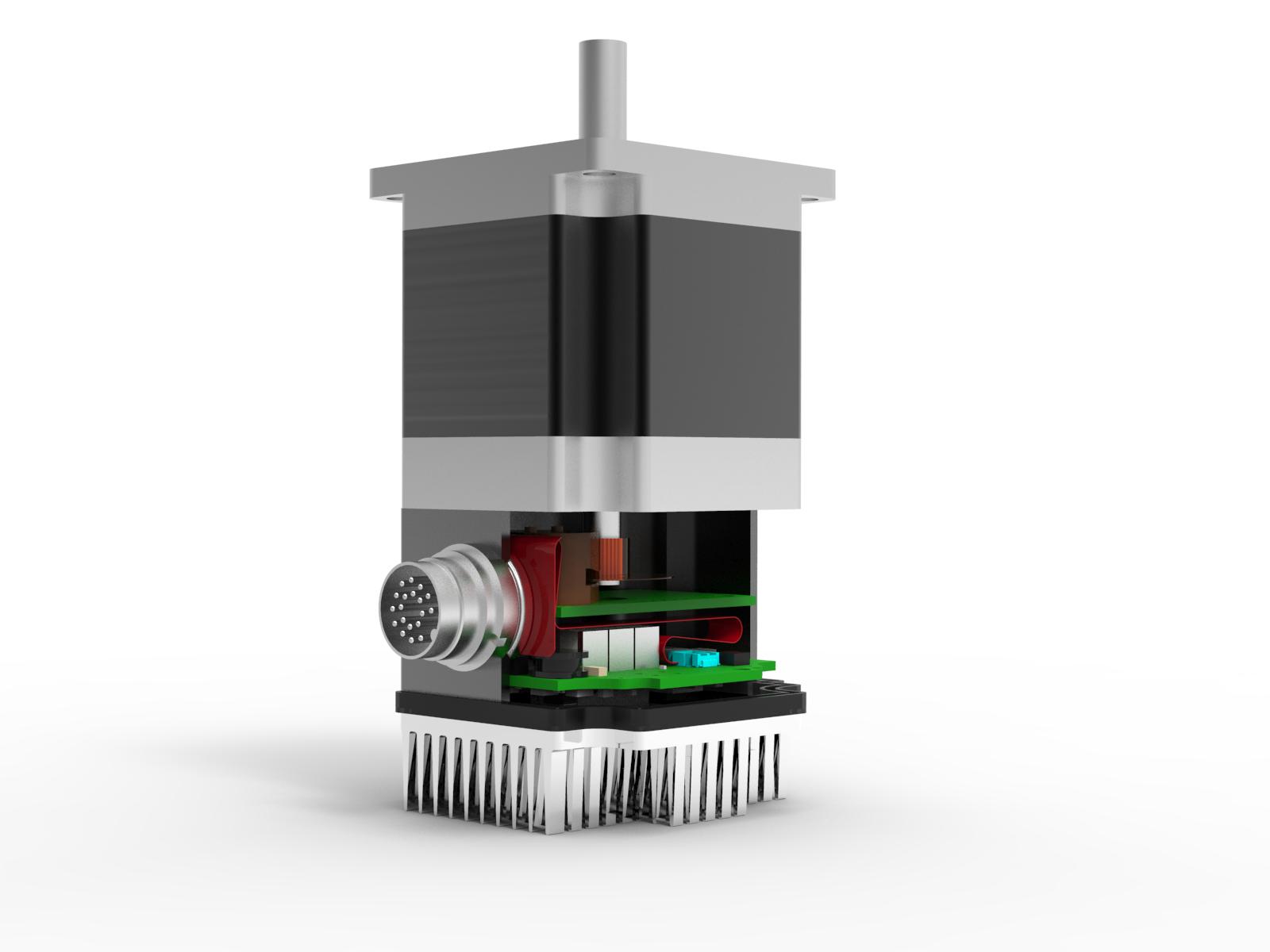
April 10 202 | Donald P. Labriola PE
These versatile, low cost and high torque motors may be used open loop or as full servos, and several levels in between. The motor stator laminate designs divide these motors into those optimized for full stepping and those optimized for micro stepping and servo operation. These differences can be easily measured with basic meters and oscilloscopes. Motor to motor variations can also be easily measured, and motor inductance at nominal speed and current can also be determined.
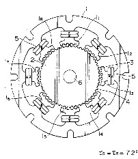
There are two distinct designs of the stator for common two-phase 1.8 degree per step motors, each with its own advantages and disadvantages. Full stepping laminates and micro-stepping laminates (of which there are many variants). The full stepping laminates have the rotor and stator teeth on the same pitch. For a 1.8 degree motor, another name is 50:50 laminate: 50 teeth on each pole cap, and stator teeth on the same 50 tooth spacing. Full stepping motors typically have a higher holding torque and a higher unpowered detent torque. The increased holding torque (for full step positions) is due to the detent torque aiding the torque at the full step positions. The detent torque is generated by having many of the rotor and stator teeth all align simultaneously, producing significantly lower reluctance path for the magnet in these motors when at the full step positions. The figure is from US5309051. This detent torque, is present even when power is removed from the windings, and may be used advantageously in applications such as continuous paper printers in that the platen has holding torque to resist motion even when powered down. This keeps the paper from unwinding on the floor when power goes out, without the need for mechanical brakes
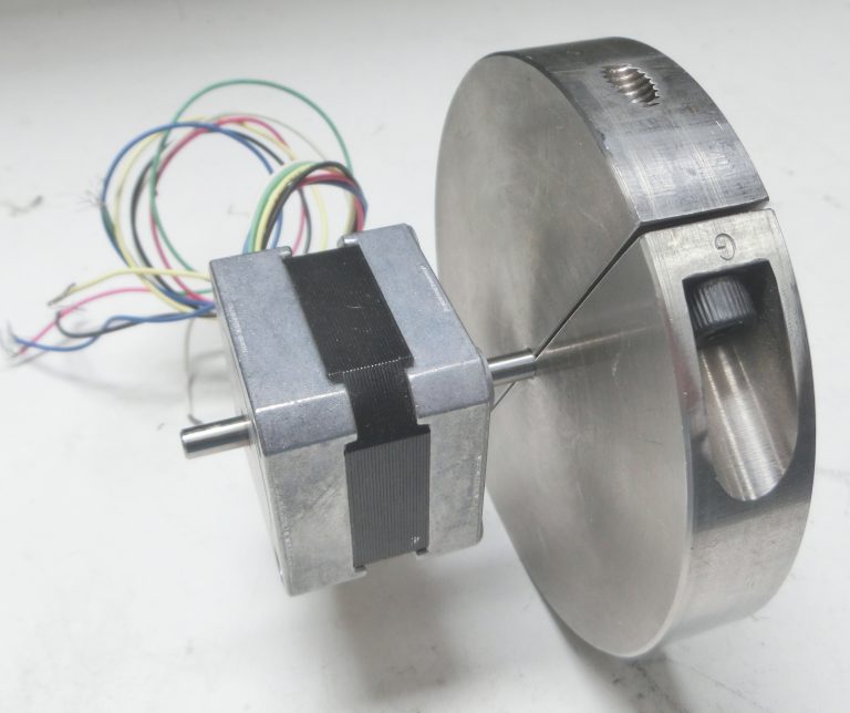
When the rotor of a permanent magnet motor is spun, the windings on the stator produce voltages due to the magnetic fields from the permanent magnet in the rotor being gated through the teeth of the rotor and stator, and producing time varying flux through the coils present in the stator. The voltages from the two windings can be viewed both versus time, and also as one winding versus the other, preferably while keeping a constant rotation speed. This is easily accomplished by spinning the shaft with a small electric drill motor. A large flywheel can also be attached to the shaft and hand spun with the output from one of the windings recorded over a several second time interval using a digital storage scope. (A USB scope which uses the memory of the PC gives good sampling rates over the long intervals). We will cover each of these techniques.
Full-step versus Micro-step optimized Motors
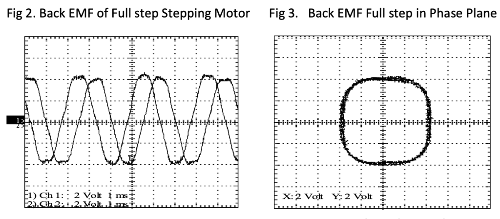
he oscilloscope channels of a 2-channel digital scope are connected to the motor and the motor is spun with a small power drill. The full step stepping motor produces a trapezoidal back-EMF when spun. The phase plane chart is almost square with rounded corners. The radius of the back-EMF pattern at a given angle represents the torque constant for that motor at that angle. The fact that the radius varies significantly with angle indicates significant variations in torque when this motor is excited sinusoidally – either microstepping or closed loop.
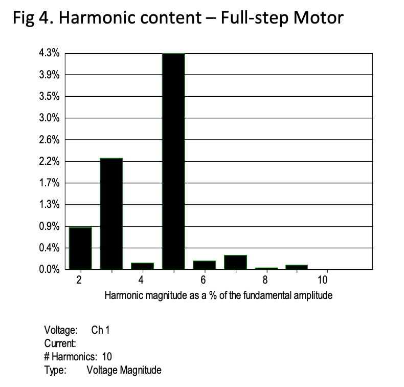
If the oscilloscope has the capability, or an offline calculation is used, a chart of the harmonic content can be obtained. The backEMF of a full stepping motor shows large 3rd and 5th harmonic content, resulting from the squaring of the waveforms due to the design of the rotor and stator teeth.
Visualizing Detent Torque
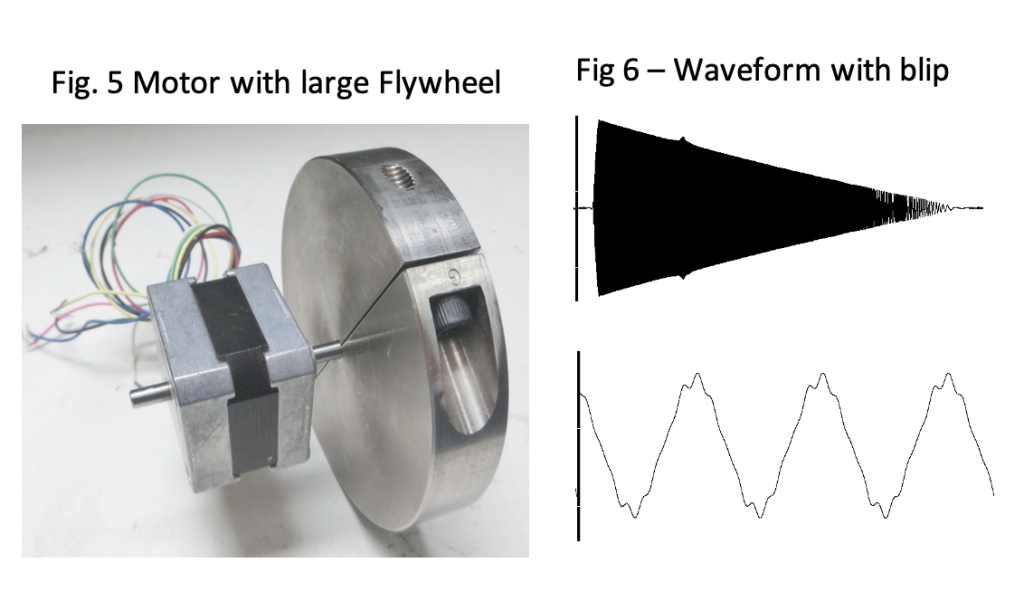
Detent torque – both magnitude and harmonic content – can be easily viewed by attaching a large flywheel (Fig.5) to the motor being tested. One of the windings is connected to a storage scope – a digital scope with deep memory – including USB oscilloscopes shown here – work well. The motor body is secured, and the flywheel is spun up by hand and allowed to slow down on its own. For the full stepping motor shown, a blip about 25% from the peak speed is visible in the top waveform of Figure 6. Expanding the blip, it appears that the 5th harmonic of the main waveform is present. The large flywheel does not significantly change its speed at the pulse rate of the detent torque, but the motor inertia and the spring of the shaft form a mechanical resonance that will resonate when the frequency of the detent torque – or one of its harmonics – hits the resonance frequency. The friction in the system gradually slows the flywheel, scanning the various frequencies. Additional harmonics may be seen if the detent torque versus angle is very steep. Lower harmonics require higher speeds to resonate. (You may need a string around the wheel like a pull start lawn mower to reach these speeds.) This sharp shape of detent may also be detected by rotating the unenergized motor by hand. The motion feels like a series of detents.
Micro Step Design
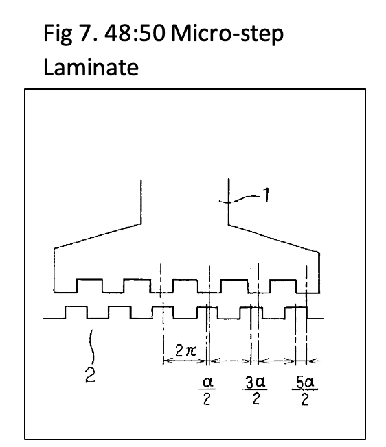
The micro-step optimized motor originated as a smoother version of the 2-phase sinusoidal drive using a split phase capacitor for the second phase, as shown in US2982872 in the first article in this series. Other variations to optimize smooth motion are shown in multiple patents, involving changes the pitch, position, and width of the stator teeth versus the rotor teeth, such as are shown in US7518270. Figure 7 shows a tooth configuration also known as 48:50 tooth spacing with 6 teeth on the stator claw (top) spaced at a wider spacing than the rotor teeth (bottom) such that they do not all come into alignment simultaneously. These styles of motors are preferred for both microstepping and for closed loop applications.
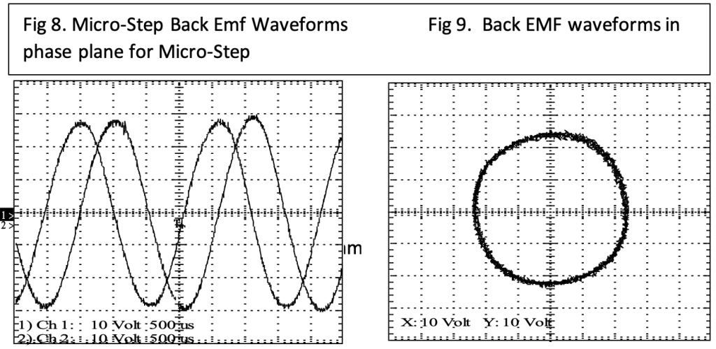
The Micro-step optimized motors produce a much more sinusoidal back-EMF, as is visible in both the time and phase plane charts. The radius is nearly constant, producing nearly the same torque (when sinusoidally driven) for all angles of rotation. This motor shows significantly smaller third and fifth harmonic content in its back-EMF.
The unenergized detent torque, which is greatly reduced in both magnitude and in higher harmonic content for the micro-step optimized motors. The detent reduction comes about avoiding the simultaneous alignment of many rotor and stator teeth. Careful choices on spacing and the width of the teeth for both the stator and rotor can help to keep the reluctance path much more constant.
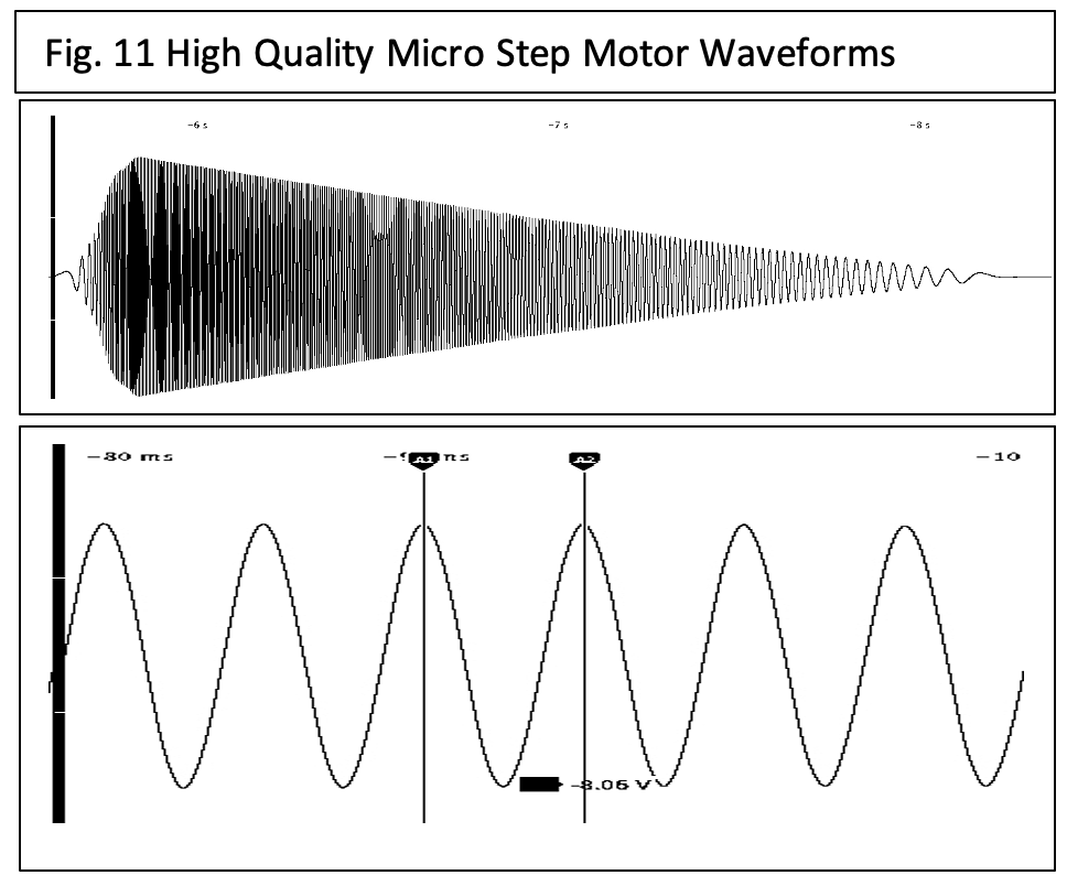
The flywheel test of the high quality micro step motor design shows a very smooth decay. The backEMF also appears much more sinusoidal, as expected.
The damping friction of the motor can be easily calculated by determining the time to decay for one time constant and calculating the flywheel inertia. This separates the detent torque from the friction.
Measuring Motor Parameters
Spinning the motor at constant speed – such as using a hand drill motor – while measuring the output from the windings can be used to measure the backEMF constant of the motor. When the backEMF is divided by the motor speed in radians per second, the numerical value for Kv is the same as for Kt in Newton-meters/Amp (assuming a sinusoidal drive). The cycle RMS value for multiple cycles gives a good repeatable measurement. The balance of the motor phases can be easily calculated. Using an oscilloscope with math functions, the product of the two phases can be determined, and the integral of the product can be taken. The integral of sin(t)*cosine(t) should equal zero when integrated over full cycles. If the phases are not 90 degrees apart, then this integral will be non-zero. This can indicate a dropped motor or mis-manufactured motor.
The inductance of the motor is also readily measured by adding a resistor across the winding of approximately the motor winding resistance (Rw) up to about 10x the winding resistance. The open voltage and frequency (Vo, Fo) are measured, the resistance (Rl) is added across the winding and the loaded voltage and frequency are measured. The open readings are used to determine the Kv (backEMF constant). The frequency for the loaded measurements are used to calculate the internal voltage, the internal resistor and inductance drop the voltage, with the current measured via measuring the voltage across the load resistor. The voltage across the internal resistor is readily calculated, and knowing the inductance voltage drop is at 90 degrees to the resistive voltage drops, the voltage across the inductor is easily calculated. Knowing the voltage and current gives the impedance, and knowing the frequency gives the inductance. A drill motor, a resistor, a VOM or oscilloscope than can measure RMS voltage and frequency, and you can measure the motor inductance under significant current load. This is a measurement much more reflective of the inductance as the motor will be operated. The motor windings have significant capacitance to the stator, which can significantly degrade the measurements of many LCR meters; probing with much lower current the capacitive shunt currents can cause bad readings.
Vl_int = Vo/Fo*Fl (Loaded internal backEMF voltage)
Il = Vl / Rl (Current through load)
Vr = Il * (Rl+Rm) (In-phase or resistive voltage)
Vinductor = (Vl_int^2 – Vr^2)^.5 (solve the right angle triangle for the voltage across the inductor
Lm = (Vinductor / Il )/(2*PI*Fl) (Impedance over electrical frequency in radians per second)
Related Posts
Operational Advantages of Integrated Motors
Operational Advantages of Integrated Motors Interesting Projects Blog April 17 2024 | Donald P. Labriola PE Combining a motor with

Integrated Hybrid Servo Motors Vs Standard Integrated Servo Motors
Integrated Hybrid Servo Motors Vs Standard Integrated Servo Motors Interesting Projects Blog April 10 2025 | Donald P. Labriola PE
Thank you for this article. It is very well written. It is very helpful to me.