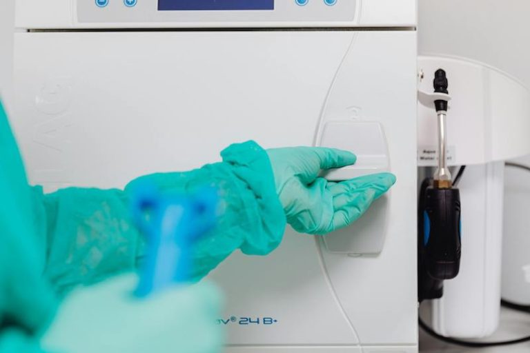
Motion Control in Medical Equipment
Interesting Projects Blog
April 19 2024 | Donald P. Labriola PE
CANopen Lets Devices Easily Communicate
Medical instruments are increasingly sophisticated, which has increased regulatory requirements and compliance testing. In the past, systems tended to use one centralized computer for motion control. This balanced the then expensive processors against the cost and complexity of wiring and interface boards that were needed to bring all the signals back to the central processor. Unfortunately, it was all-too-easy for electromagnetic noise from a nearby walkie-talkie to grind a whole machine to a halt. Additionally, sharing so many diverse real-time operations on a single processor required much more testing. That is, whenever any module or functional unit was changed in the system, all of them needed re-validation.
A better approach, called distributed processing, involves placing the computers close to what they are controlling. This minmizes cabling, improves reliability, and reduces cost Distributed processing also helps isolate the hardware and the software in each of the modules from the rest of the system.
Large gystems often group multiple servo axes, along with their embedded processors, into modules. Common groupings would include a sample presentation module ( which lets technicians introduce bodily fluids and the like to the instrument in a variety of bar-coded sample containers), a sample transfer and dispensing module, and a consumables-handling module. But how does the central processor control the distributed servo axes with devices such as grippers, small cranes, and pumps so they know when, where, and how fast to move?
The answer comes from a protocol called Controller Area Network (CAN), first implemented by Bosch in the automotive industry for critical applications such as brake-skid control. Here, protocol is defined as a set of rules used by controllers to send data across small networks. CAN allows bus lengths up to 40-m long operating at 1 Megabit/sec. It handles both the physical and data link layers, with automatic error detection and retry, providing a reliable inter-face between modules without the need for software intervention
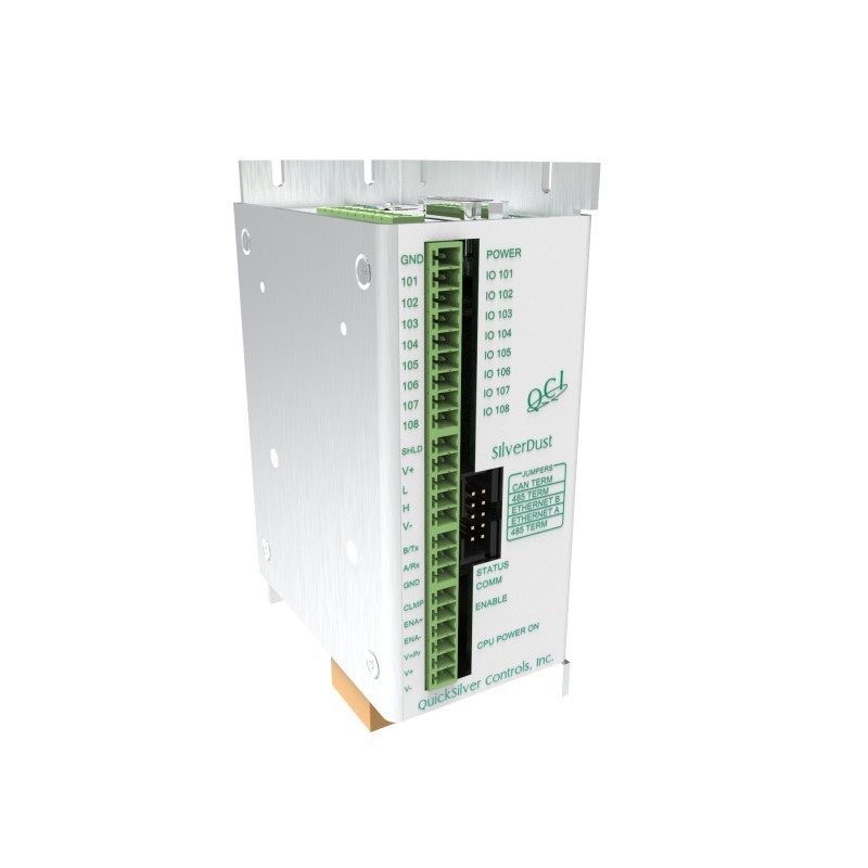
Many processors already include the CAN inter-face peripheral in the same manner as they include a serial port. Only a transceiver and connect.or must be added. The basic CAN bus consists of two wires in a twisted pair. Both ends of the bus have terminating resistors to quickly bring the bus to a “passive” state (where both wires are at the same voltage) when none of the devices ( such as grippers) connected to the bus are actively transmitting. Each device ( or node) is connected to the two wires of the CAN bus, which lets any node send or receive messages.
Above this hardware level the system still needs a way to agree upon what types of messages are avail-able to it, how messages are formatted, and how to use them to specify, start, stop, and monitor the various motions needed. CANopen has established a set of specifications covering these needs. CANopen is an “open” protocol, meaning it is openly published and manufacturers don’t need a license to use it
CANopen includes a range of documents from hardware specifications (DS-102), to standard message identification numbers and communications (DS201-207) and standard Objects used to configure CA.1-Jopen (DS:301-,’302). At the top level are the profiles which define how to communicate and the standard functions included in a conforming drive. as well as how parameters an, configured. These pro-files include IO Modules ( CiA-101 ), Drives and Motion Controls (CiA 402), and more spesific areas such as “medical diagnostic add-on modules: Electrocardiogram” (CiA425).
A big advantage to CAN open is that any medical manufacturer can use it. This makes it easy to mix and match components from different suppliers. Another advantage is the protocol 611pports millisecond-level motion timing, so equipment can ope1ate in a real-tin1e, speedy manner, depending on small and well-determined delays. It is the real-time capability of the protocol and its inherent e1rnr handling and fault confinement that makes this standard so applicable for medical devices.
A good example of its use comes from the Innova automated microbiological specimen processor from Dynacon Inc. This machine has 21 motion axes, grouped into five modules. The design required that coordination among axes could change, depending on specimen type and laboratory workflows. All modules are controlled by a central unit communicating via CANopen’s application layer. Each of the servo axes also has its n’An CA.1.’fopen chip. The system engineer can easily program the application layer to account for modules being added or removed. That’s wh.v rely-ing on CANopen, instead of developing a custom solu-tion. reduces costs, risks, and development time.
In the Innova, CA.””iopen supports vdrious motions. The &l)ecimen processor selects a sample tray and an arm moves down to uncap a sample, and, in some cases. dilute it Coordinated motions include a small crane moving side to side, and the table moving back and forth. A device draws a pattern with the sample material onto a petri dish, covers the dish, and then places everything in a controlled temperature to determine the infection. The Innova operates at about 1OO samples/hour.
Under the hood of CAN
The protocol’s real-time capability comes from a combination of 1 MB /sec communications rate, short data packets for sending bits of information ( comprising Os and ls) through the bus, and the prioritization of the packets by nondestructive bitwLw arbitration, which makes sure all the data gets through intact. This method contrasts to that of Ethernet, in which there is no data arbitration. Several devices might all try to “talk” at the same time, in which case they all have to shut up (the data is destroyed) and wait before trying again.
CANopen uses what is called the identifier frame of the data packet for arbitration. Identifier frames comprise either 11 or 29 bits, and up to 8 byt:es of data. Identifiers have the dual role of deciding which packet takes priority and of identifying packet contents. To send a packet, a node (in this case, the embedded processor in each servo axis or the master computer) writes the data to the CAN peripheral. The hardware waits until the bus has been quiet (passive state) for a mininum time and then asserts a st.art-of-frame bit onto the bus. The hardware supports a nondestructive collision avoidance mechanism which arbitrates messages from multiple nodes based on the priority that has been preassigned to each message. The high-est priority message is transmitted with no extra time incurred by the arbitration process.
The small packet size of 8 bytes reduces the latency time – how long a device has to wait get the next message in. This minimum, the delay for a high-priority message (such as an error message), while a lower-priority message (such as a switch has opened) is already under way. At a 1 MB data rate, packets take between 47 and 135 microseconds according to the number of data bytes being sent Packets are multicast; that is all nodes can receive them simultaneously. Each node on the bus then acts upon the data or the packet according to the function and configuration.
Message Standardization
CANopen protocols are available through CAN in Automation (CiA), an international group that develops and supports CANopen and other CAN-based higher-layer protocols ( www.can-cia.r.ny). In CANopen, the data to be transferred is identified through a 16 bit data dictionary, which includes data sizes and types. The dictionary al-lows for the identification of networked devices and their properties.
Here, communications are divided into three major classifications: network management (NMT), service data objects (SD0), and process data objects (PDQ). NMT includes the capability to change node states from that of being configured to being active. It also provides for error, time synchronization, and the “heart-beat” messages, which indicate the status of nodes. SDOs are single-node to single-node communications.
PDOs send repetitive data from one node to one or many other nodes. Data exchanges can be triggered by time or by events ( changes in the data) and can be synchronized or asynchronous. They are useful for monitoring IO and updating sensor values or
motor positions.
Related Posts
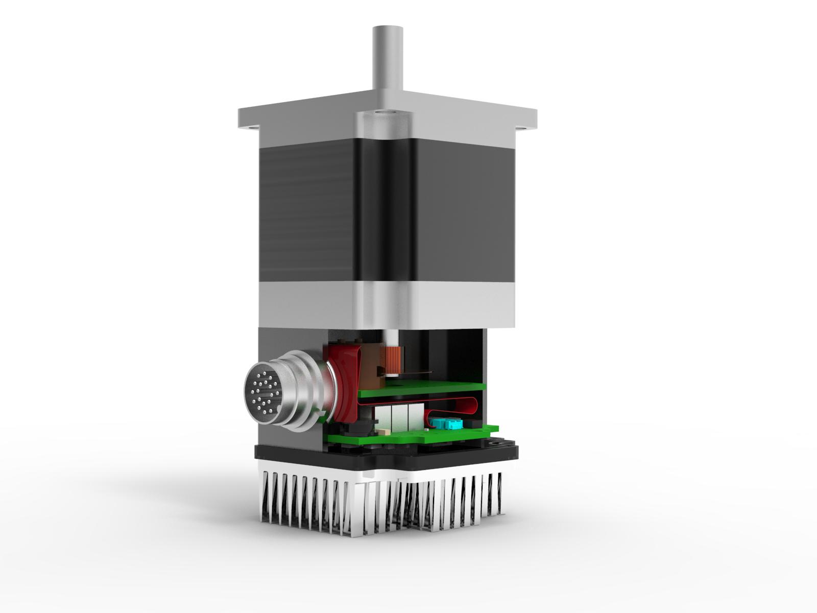
Operational Advantages of Integrated Motors
Operational Advantages of Integrated Motors Interesting Projects Blog April 17 2024 | Donald P. Labriola PE Combining a motor with

Integrated Hybrid Servo Motors Vs Standard Integrated Servo Motors
Integrated Hybrid Servo Motors Vs Standard Integrated Servo Motors Interesting Projects Blog April 10 2025 | Donald P. Labriola PE